Type of protection “p” pressurization
EMMUA 214 States: Page 15
Page 24
3.3.1 Definition
Type of protection ‘p’, pressurised equipment, is the technique of guarding against the ingress of the external atmosphere into an enclosure by maintaining a protective gas therein at a pressure above that of the external atmosphere. 3.3.2 Standards and selection
i) Current standards
IEC 60079-2 (EN 60079-2) Explosive atmospheres Part 2: Equipment protection by pressurized enclosures ‘p’;
IEC 60079-13 Equipment protection by pressurized room ‘p’
IEC 60079-16 Electrical Apparatus for Explosive Gas Atmospheres Part 16: Artificial Ventilation for the Protection of Analyser(s) Houses.
ii) Superseded standards
EN 50016 Pressurized apparatus ‘p’;
BS 5501 Part 3 Pressurized apparatus ‘p’.
iii) EPL/Category and zones of use
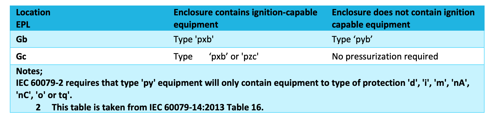
Protection by pressurisation is subdivided into three protection types (‘Px’, ‘py’ and ‘pz’). Such equipment may have the alternative markings of ‘pxb’, ‘pyb’ and ‘pzc’. Equipment is selected based upon the external explosive atmosphere, the potential for an internal release and whether the equipment within the pressurised enclosure is ignition-capable.
Table 8: Pressurisation - determination of type of protection (with no flammable release within the enclosure)
3.3.3 Details
i) Pressurising medium
The pressurising medium should be from an area free from flammable gas. A protective gas such as nitrogen may be specified.
Cautionary Note on Asphyxiation: An inert gas such as nitrogen may be used to purge or pressurise some equipment. Analysers in analyser houses may use nitrogen as a backup for operating air. An unoccupied analyser house in operation could have a quantity of nitrogen inside. Personnel should therefore be made aware that breathing an oxygen depleted gas (less than 16% oxygen) can result in death from asphyxiation.
ii) Warning Notices
Warning notices should be fitted or a timed interlock installed to ensure that hot surfaces have cooled and capacitors have discharged prior to the door being opened.
iii) Spark Arresters
It may not be feasible to duct issuing air from purged equipment into a safe area. A spark flame arrestor is then required in the outlet air duct.
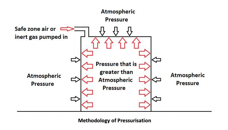
Pressurisation is a simple technique for providing explosion protection. If the interior of an enclosure is at pressure above that externally, any flammable gases around the enclosure will be prevented from entering the enclosure.
Components which are a source of ignition i.e. they produce arcs/sparks or hot surfaces, are permitted within the enclosure and clearly, safety is dependant on the maintenance of the safe gas.
The safe gas is the medium which segregates the flammable gas from the source of ignition, and its continued presence will be confirmed by an approved/certified “fail-safe” control/monitoring system.
A slight over-pressure is usually adequete to maintain safe operation.
Definition
Pressurisation is defined as:
The technique of guarding against the ingress of the external atmosphere into an enclosure or room by maintaining a protective gas therein at a pressure above that of the external atmosphere.
This method of protection is suitable for use in Zone 1 and 2 areas and sub-divides into 3 protection types which are Ex px, Ex py and Ex pz:
- Ex px can be used in a Zone 1 & 2 area if the equipment contains ignition capable equipment
- Ex py can be used in a Zone 1 & 2 area if the equipment does not contain ignition capable equipment
- Ex pz can be used in a Zone 2 area only if the equipment contains either ignition capable equipment or does not contain ignition capable equipment.
Protective Gas
Most common protective gas used is Instrument Grade air. Air used is dry, oil free and filtered of small particles.
Under certain circumstances an inert gas, such as nitrogen, can be used where flammable materials are brought into the purged enclosure apparatus.
Examples of this application are on-line analysers or at-line laboratory analysis.
When using inert gas as a purging gas, great care needs to be taken when working in the purged enclosure as there will be no air to breath, resulting in a fatal incident.
Alarm warnings, maintenance procedures and permits to work all need to recognise the danger to maintenance personnel in the work area.
If the purged enclosure is inside a building, then man entry conditions need specified for confined space entry. Purge System Operating Conditions
Three purge systems are considered below:
- Static pressurisation
- Leakage Compensation
- Continuous Flow
Static Pressurisation System
Static pressurisation allows for the design of apparatus to be purged and pressurised outside the hazardous area, where a source of purge gas is not available.
The pressurised apparatus can then be taken into the hazardous area.
Static purged apparatus must be leak tight otherwise safety gas will be lost.
Leakage Compensation System
Where an enclosure cannot be totally sealed, a supply of protective gas is continuously applied to the enclosure to compensate for gas leakages.
In this protection method, a purge control system attached to the enclosure and, separately supplied with gas and electrical power usually controls the enclosure purging and the installed apparatus power-up.
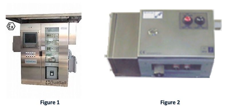
There are several manufacturers of purge control systems which carry certification to allow purge gas control under defined conditions. Figure 1 (below) shows an enclosure with a purge control module installed on its left hand side. Figure 2 (below) shows a purge control module.
The enclosure will start with a fast purge to dilute and remove any possible flammable mixture inside the enclosure. This gas flow is controlled by a solenoid operated valve (SOV).
As long as the enclosure pressure and purge gas flow rate meet pre-set conditions, the purge control module shall time-out a pre-purge period. Pre-purge time-out period is set according to the size of enclosure and conditions laid out in the hazardous area certification documents.
After a successful time-out period, the purge control module switches the protective gas flow into Leakage Compensation mode The fast purge SOV is powered off, leaving a protective gas flow set by an orifice restriction. The protective gas flow rate and enclosure pressure will drop off.
The enclosure pressure shall not fall below 50Pa (0.5mbar) above the atmospheric pressure surrounding the enclosure; important when enclosure is in a purged building!
When the enclosure pressure drops below the 50Pa level, a pressure switch contact will open and remove electrical power to the apparatus being purged. The isolation of power will remove electrical source of ignition.
Signal wiring to the Control Room, or other connected equipment, will also be isolated.
Signal wire isolation is to prevent electrical energy being routed from the control room into a potentially hazardous area. Where dilution is required there will be no ignition capable apparatus. If there is ignition capable apparatus then separate containment enclosures are required.
Continous Flow Purge System
This system of purging operates in a similar manner to Leakage Compensation except that the protective gas flow is maintained after the pre-purge time-out.
Protective gas flow rate, operational purge flow rate, low-pressure switch operation and electrical isolation are all present in this purge system.
Continuous Flow purge system is a method of protection used in applications where a continual dilution of atmosphere is needed or hot surfaces require cooling.
Where dilution of hazard mixtures is required there will be no ignition capable apparatus. Separate containment enclosures are required.